F-1 engine ignition sequence |
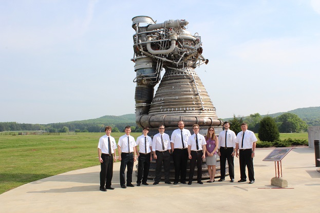 The row of engineers in front of the F-1 rocket engine illustrates the sheer size of the engine. The F-1 produced about 680 metric Tons of thrust. Five of these engines were used to lift the 2800 metrics Tons heavy Saturn V from the launchpad.
|
 The five F-1 engines at the base of the first stage (S-IC stage).
Scanning credit to Kipp Teague |
|
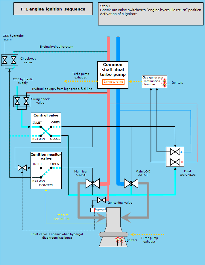
The gigantic F-1 rocket engine is a very complex machine with a network of valves, lines, and pipes around a thrust chamber and turbopumps to feed the thrust chamber with liquid oxygen and RP-1. In order to ignite the gigantic F-1 engine, an elaborate ignition sequence had to be devised to bring every component of the engine online in a proper sequence at just the right moment. Two main steps in the ignition sequence can be distinguished:
|
 |
|
START OF IGNITION SEQUENCE
he thrust chamber of the F-1 engine is fed through two fuel ducts and two LOX ducts, each equipped with a valve. In the drawings only one main fuel line and one main LOX line are depicted. The check-out valve and the 4 pyrotechnic igniters are activated by an ignition sequencer. The next sequence of events are interrelated. The control valve, for example, is activated when the igniters have burned through electrical links.
|
 |
|
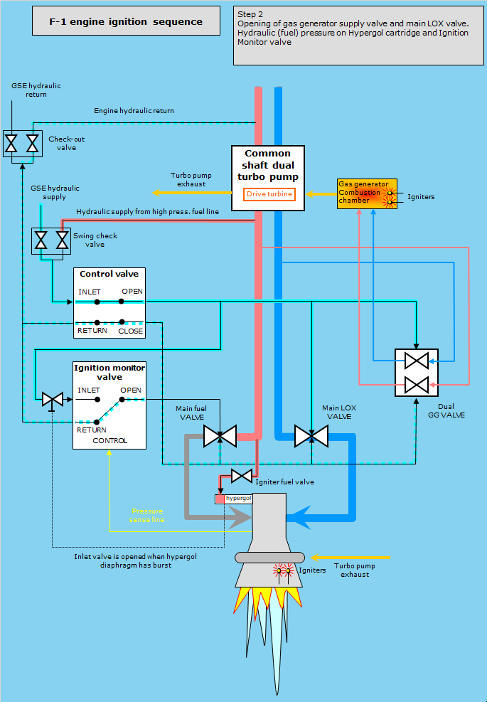
START OF PROPELLANT TURBO PUMP BUILD-UP OF PROPELLANT DISCHARGE PRESSURE The control valve is activated, and hydraulic pressure is applied to open the main LOX valves and the gas generator propellant supply valve.
|
 |
PRIMARY IGNITION
|
 |
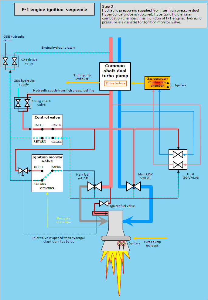
TRANSITION TO MAINSTAGE
|
| Acronyms | |
|---|---|
|
GSE Ground Source Equipment
GG Gas Generator LOX Liquid Oxygen RP Rocket Propellant |
|
| References |
|---|
|
Site Map |
References |
Change History
|
All pictures and drawings contained on and through these pages are the author's, unless otherwise noted. No unauthorized reproduction without permission. |